The System Management Software provides graphical interfaces for online management of system information, technical guides on how to perform patching of cords, generate real-time alarm messages, monitor the full link and provide all the necessary analysis management tools. Users are able to capture the system information and generate reports for database analysis.
• Displaying information of the whole system which include structure information, building information, floor information, room information, management room information, rack and equipment information
• Tracing vital information for switch port status, outlets layout and its physical location.
• Confirming changes in unguided patching operations and initiating alert to the users
• Guiding the user in managing work orders, logging events and creating visual network topology
• Easy access to the software by web browzer
• Maintaining up-to-date network documentation
• Identifying the physical location of the active equipments connected to the network for better asset management
• Multiple language support
Intelligent Management System
• No need to do the database change manually.
• All link information can be managed professionally
• All link information can be monitored online
• Full links monitored for all the Switch ports and workstations
• Any status change for the patch cords can be monitored online
• Events log and recording of link status
Guide for patching
• Guide how to connect the patch cords
• Guide how to disconnect the patch cords
• Guide how to X-patching two patch cord connection
• Prompt patching guide.
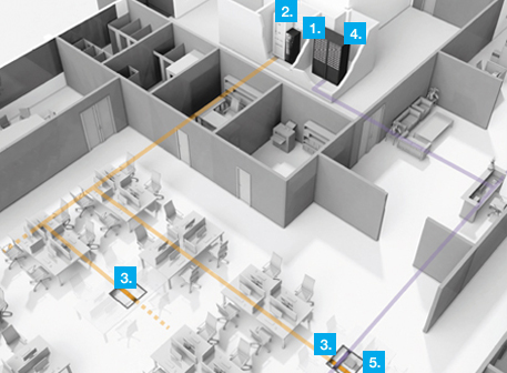
Full link with network facilities and outlets
• Floor layout can be displayed according to the outlet aq2 location
• Full link can be displayed correctly from the switch port to workstations
• Workstation information can be displayed online
Different Alarm Level
• IMU offline
• Patch Panel offline
• Un-authorized Patching
• Un-authorized Patching with LED flashing
• Alarm can be shown in the IMU LCD display
• Alarm windows can be displayed
Different link status are displayed with different colors
• Port status
• Outlet status
• View Mode
This mode only provides viewing of the whole system. It does not have any work order functionality and is designed for the people who are efficient in the cabling and network system.
• Work order mode
Work order mode is designed for system professionals, including all functions in View Mode. It can initiate order to connect/disconnect the patch cords and deal with the alarm message. After the work order is made, the engineer can perform the patching of the cords indicated by the LED flashing. When fault occurs, system also can receive an alarm message.
• Engineering Mode
It is designed only for the engineering professionals. All database set up and system configuration should be completed in this mode. The Engineering Mode will have the highest level of authority as compared to View Mode and Work Order Mode view. After installation of DICS software, the user can start-up this mode and the software can perform auto-scanning. During the configuration, the user can set up the outlet location, link information, equipment management, information of workstations, user management.
Login Interface

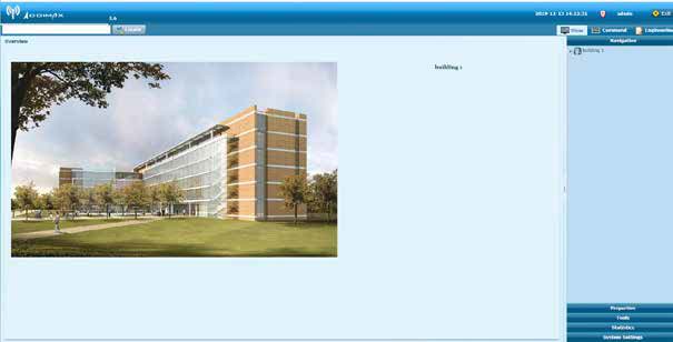
Software Interface
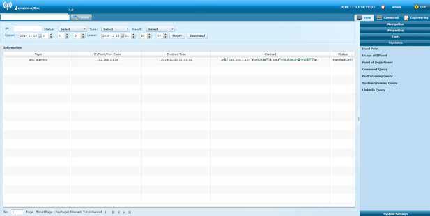
Warning Interface
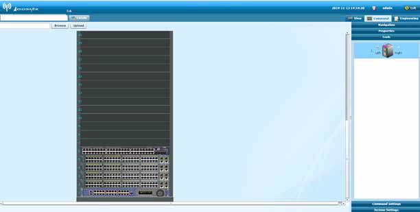
Order Interface
• Windows XP Professional (32bit), Windows Server 2003 (32bit) or Window 7 (32bit)
• Microsoft .Net Framework 4.0(Already included in the software)
• Java Develop Kit 1.6.0.26(Already included in the software)
• MySQL 5.5.13(Already included in the software) or Microsoft SQL Server 2008 R2(In charge)
• Client Environment Requirements
• Microsoft IE 6.0 minimum
• Google Chrome 14.0 minimum
• Adobe Flash Player 11 must be installed on all the above browsers.
| Part NO. | Description |
| AD-DICS | DICS Cabling system management software |